A coaxial propeller scheme is an advanced power plant architecture in which two or more propellers are placed on a common axis and rotate in opposite directions. This configuration not only eliminates undesirable aerodynamic effects, but also significantly increases the efficiency of the entire propulsion system.
How does the coaxial system work?
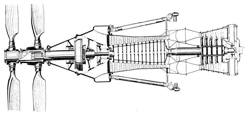
Structurally, the implementation of a coaxial scheme requires the use of a specialized gearbox capable of converting the unidirectional rotation of the engine shaft into the counter-rotation of two coaxial shafts. At the same time, the blades of the front and rear propellers have opposite geometric pitch, which provides a total thrust in one direction, despite the antiphase rotation.
Reactive torque compensation is a key advantage
One of the main challenges when using a single propeller is the reactive (or torsional) moment. According to Newton's third law, when torque is transmitted from the engine to the propeller, the engine itself experiences an equal and opposite effect. It tends to turn the aircraft around the longitudinal axis, especially at maximum power.
In a coaxial system, the moments created by each of the propellers are mutually balanced. As a result, the reactive torque is practically reduced to zero. This eliminates the need for additional aerodynamic or structural measures to parry the moment, such as asymmetric tail assembly or the use of differential aileron control.
Reducing the diameter of propellers is the path to high speeds
Another advantage of the coaxial scheme is the ability to reduce the diameter of each of the propellers while maintaining the overall thrust. A smaller diameter reduces the circumferential speed at the ends of the blades, which moves them away from the threshold of the wave crisis. This is especially important when reaching high cruising speeds, when local sections of the flow on the blades can transition into the supersonic region, causing shock waves, a sharp increase in drag and loss of efficiency.
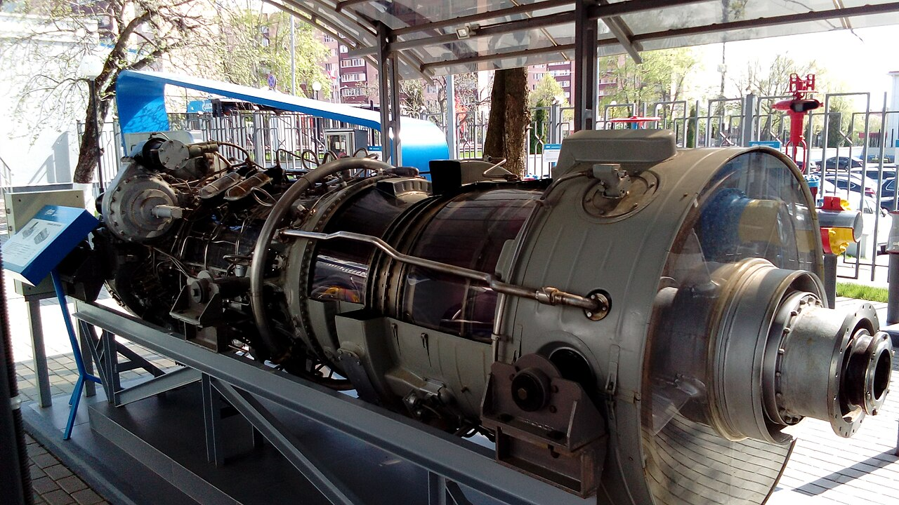
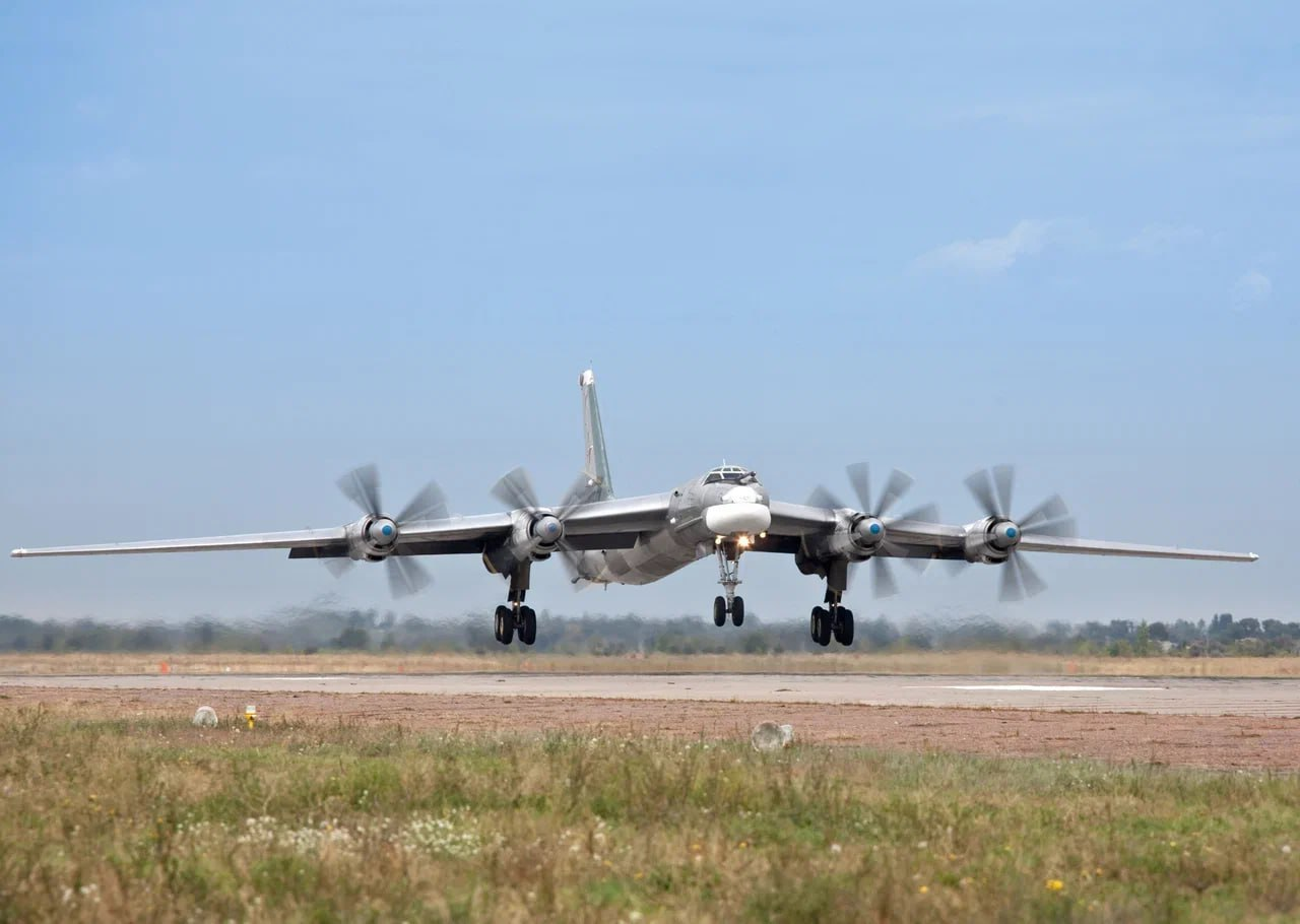
Real example: Tu-95 and NK-12 engine
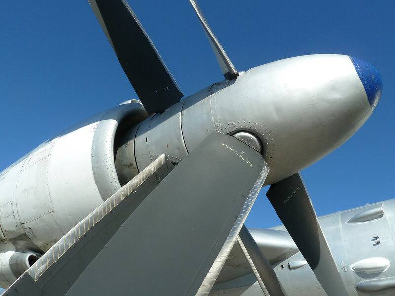
The most striking example of the practical application of the coaxial scheme remains the Tu-95 strategic long-range bomber, equipped with NK-12 turboprop engines. These engines, developed in the USSR in the 1950s, are still considered the most powerful serial turboprop installations in the world. Thanks to the AV-60N coaxial propellers with a diameter of about 5.6 meters, the Tu-95 is capable of developing a cruising speed comparable to the speed of some jet aircraft of that time - up to 830 km/h.
Experts note that it was the coaxial layout that made it possible to achieve this level of speed without switching to purely jet propulsion, while maintaining the fuel efficiency characteristic of turboprop engines.
Read more materials on the topic:
- Tomsk scientists have created a compact rotary engine for drones with a capacity of 36 hp
- Will Russia create a competitor to Boeing and Airbus?
- Russian Tu-95MS strategists conducted an 11-hour air operation in the Pacific Ocean
Комментарии